What it is
Tooling designed around your part — and around how it will be made
A tool or die is only as good as its engineering. We design injection moulds, press tools, dies, jigs and fixtures with the whole production picture in mind: cycle time, part quality, tool life, maintenance and cost. You get a design that a toolroom can build without guesswork.
- Design-for-manufacture feedback on the part before the tool is committed.
- Full 3D tool models plus 2D detail drawings with GD&T and a bill of materials.
- Standard mould-base and component libraries (DME, HASCO, Misumi, Meusburger).
- Support through tool tryout, sampling and design revisions.
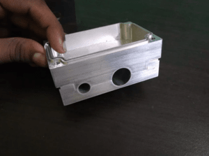
Capabilities
Tooling we design
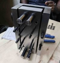
Injection mould tools
Single and multi-cavity, family moulds, hot and cold runner, with gating, ejection and conformal-style cooling worked out.
Press tools & sheet-metal dies
Blanking, piercing, bending, forming and deep-draw tools for sheet-metal components.
Progressive dies
Multi-station strip layout, carriers and pilots for high-volume stamped parts in one press stroke.
Die-casting dies
Dies for aluminium and zinc pressure die casting, with runner, overflow and cooling design.
Compression & transfer moulds
Tooling for rubber, silicone and thermoset compression and transfer moulding.
Jigs, fixtures & gauges
Assembly, welding, drilling and inspection fixtures, plus check gauges tied to your GD&T.
How we work
Our tool & die design process
Part & requirement review
We review the part model, material, tolerances, cosmetic needs and target volume to fix the tooling strategy.
DFM & feasibility
Draft angles, wall sections, undercuts, parting line and gate locations are checked and fed back before design starts.
Tooling concept & layout
Cavity count, mould-base size, parting, slides and lifters, and the overall layout are agreed with you.
Detailed 3D design
Core and cavity, ejection, cooling, gating, venting and standard components are modelled in full 3D.
2D drawings, GD&T & BOM
Manufacturing drawings for every component, tolerances, and a complete bill of materials for the toolroom.
Tryout support & revisions
We support first sampling, review results and design any corrections to get the tool signed off.
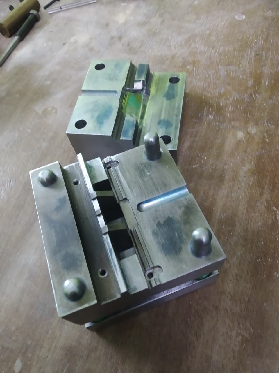
Deliverables
What you receive
A complete design package your toolroom can quote and cut from, in the formats you work with.
Why it matters
Good tool design pays off every cycle
Faster cycle times
Balanced runners and effective cooling shave seconds off every shot — and rupees off every part.
Consistent quality
Correct venting, gating and ejection mean fewer short shots, flash, sink and warpage.
Longer tool life
Right material selection, hardness and cooling keep the tool producing for its full expected life.
Lower total cost
Fewer tryout loops, fewer engineering changes and lower reject rates over the tool's life.
Software & standards
Built to industry standards
We design in SolidWorks, Siemens NX and Creo, using standard mould-base and component catalogues so your toolroom can source parts off the shelf.
Industries
Who we work with
FAQ
Common questions
Do you also manufacture the tool, or only design it?
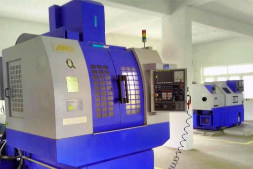
Yes — we manufacture the tool as well, with full in-house capacity to build it. We machine and finish the mould or die, assemble it and run tryout, so you can take a design-only package or a complete design-to-tryout, ready-to-run tool.
What files do you need to start a tool design?
A 3D CAD model of the part (STEP, Parasolid, IGES or native), the target annual volume, the moulding or forming material, and any critical dimensions or cosmetic requirements. If you only have a physical sample we can 3D scan and reverse engineer it first.
How long does an injection mould tool design take?
A single-cavity mould design is typically 1 to 2 weeks after DFM sign-off; multi-cavity, family and progressive tools take longer depending on complexity.
Can you improve or fix an existing tool?
Yes. We review existing tools for short shots, flash, warpage, sink, cooling and cycle-time issues and design corrective modifications, including new inserts, revised gating and cooling changes.
Related services